Crafting a dissolve effect in Metal and SwiftUI
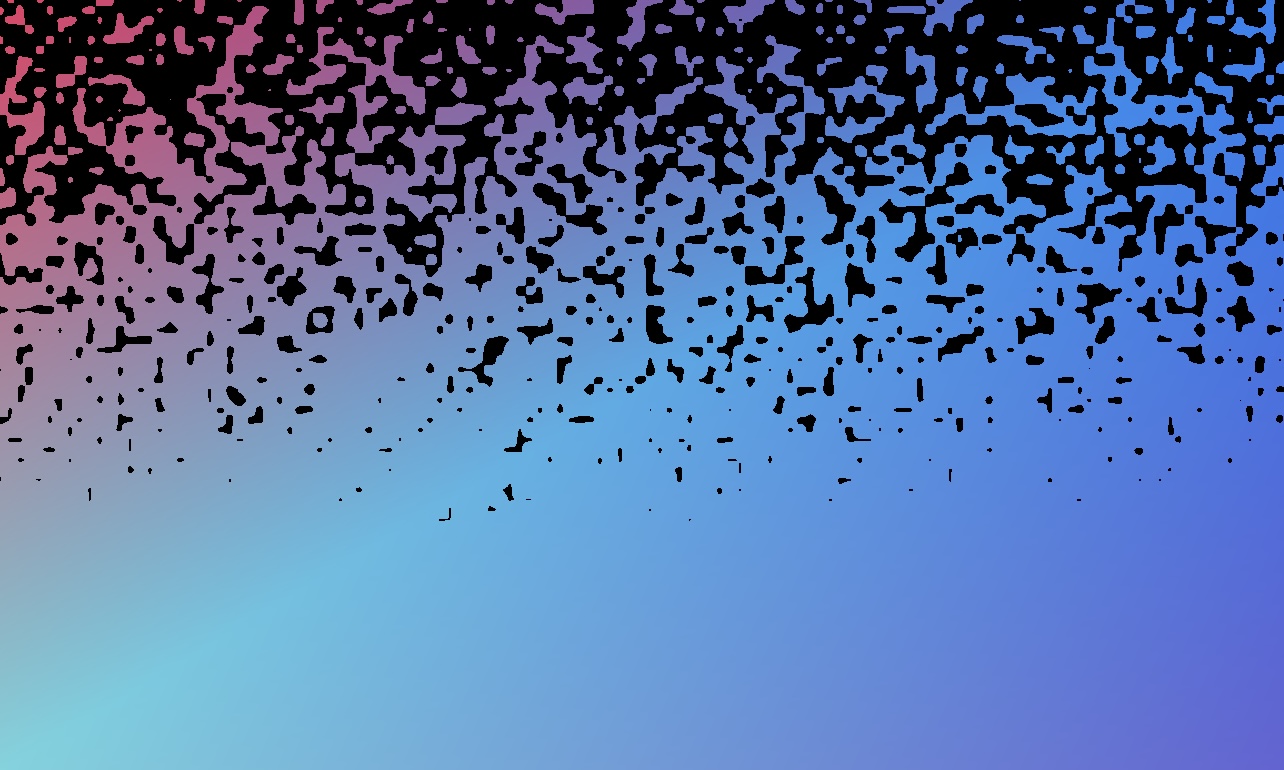
Today I would like to take a closer look at the rendering pipeline in Metal. We’ll explore how to create an engaging dissolve effect while learning about the fundamental concepts of Metal’s rendering pipeline. Through this practical example, we’ll understand how fragment shaders, noise functions, and alpha thresholds work together to create a compelling visual effect.
Theory
First, let’s familiarise ourselves a little with the idea of how the dissolve effect will work and what we need to do that. The alpha component for each fragment is evaluated as a simple step function. We will generate random values based on UV (normalized coordinate) of the fragment with some noise function and see whether they exceed some threshold value or not. If they are then the we say that the fragment is visible, otherwise it’s not.
The visibility threshold is a variable that changes during the animation period. The variable representing the dissolve progress is independent of time, but depends on the distance to the next vertex (we will talk about this in a moment).
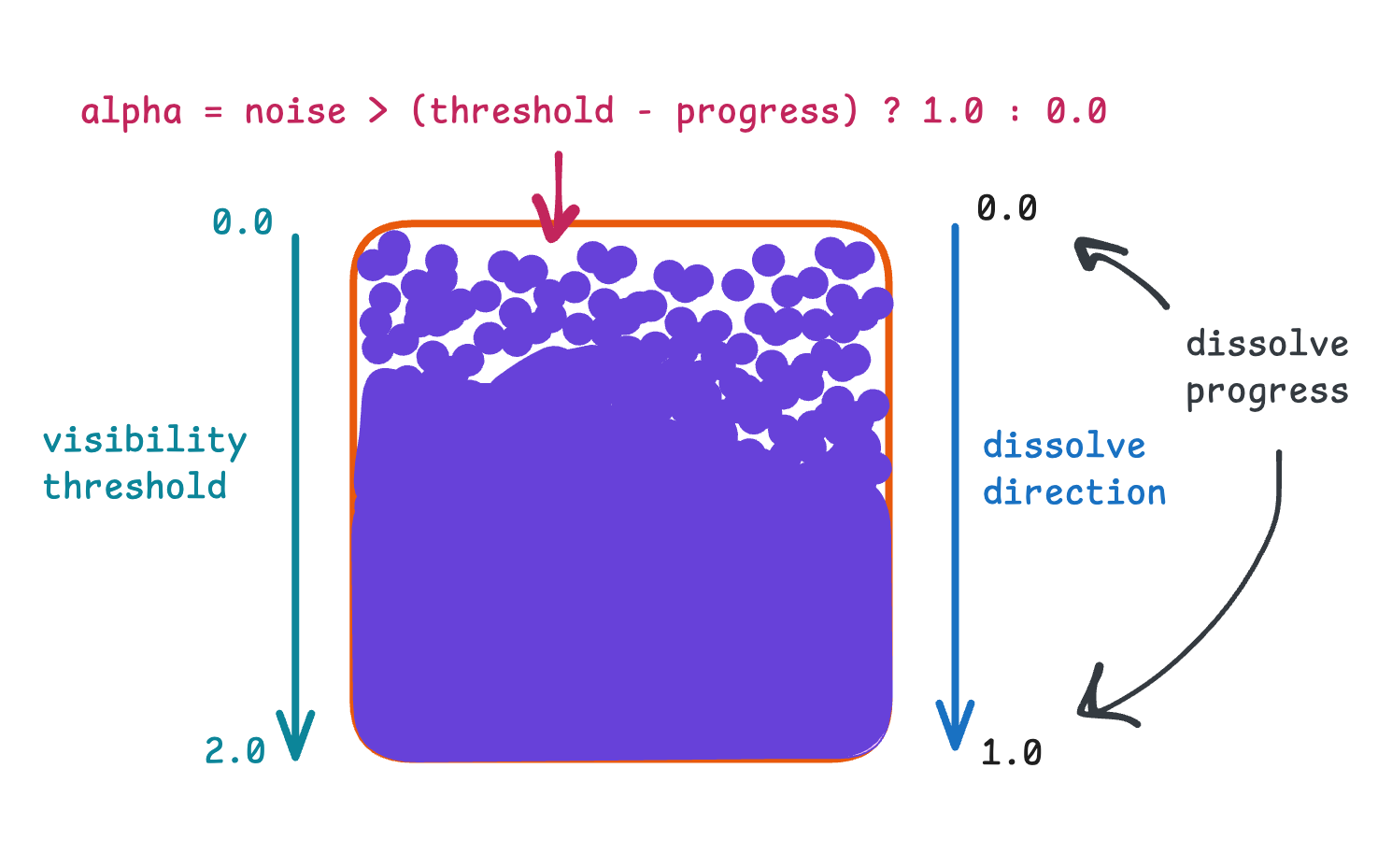
I know this may seem a little bit confusing at first glance, so let’s break down this logic with a small example.
First and foremost, let’s highlight the formula for calculating the alpha component separately:
alpha = noise > (threshold - progress) ? 1.0 : 0.0
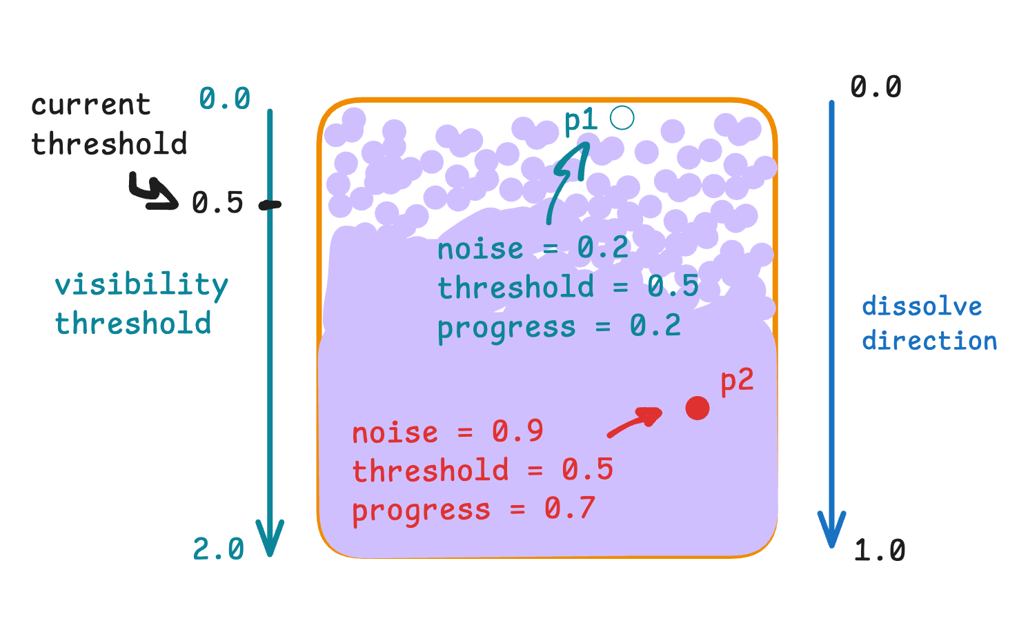
Take two random points at the texture, one is invisible and the other one is visible. For both points (as well as the others) the visibility threshold is the same (because it depends on time, not on point position). But the dissolve progress is different for them, because it depends on the position of the point, not on time. The noise parameter can be anything, specifically for these points the values were as shown in the picture.
Well, it’s better to name the dissolve progress as dissolve delay, but we will keep it as is.
Now it remains to calculate the alpha for each point. For p1 the calculation is as follows:
alpha = 0.2 > 0.5 - 0.2 ? 1.0 : 0.0 = 0.0And for p2 it’s:
alpha = 0.9 > 0.5 - 0.7 ? 1.0 : 0.0 = 1.0And these calculations are performed for each fragment, determining its visibility. As the animation moves towards it’s ending, more and more points will fall into the range where their noise parameter will give zero alpha.
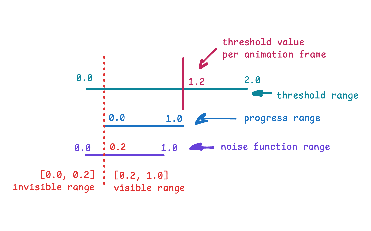
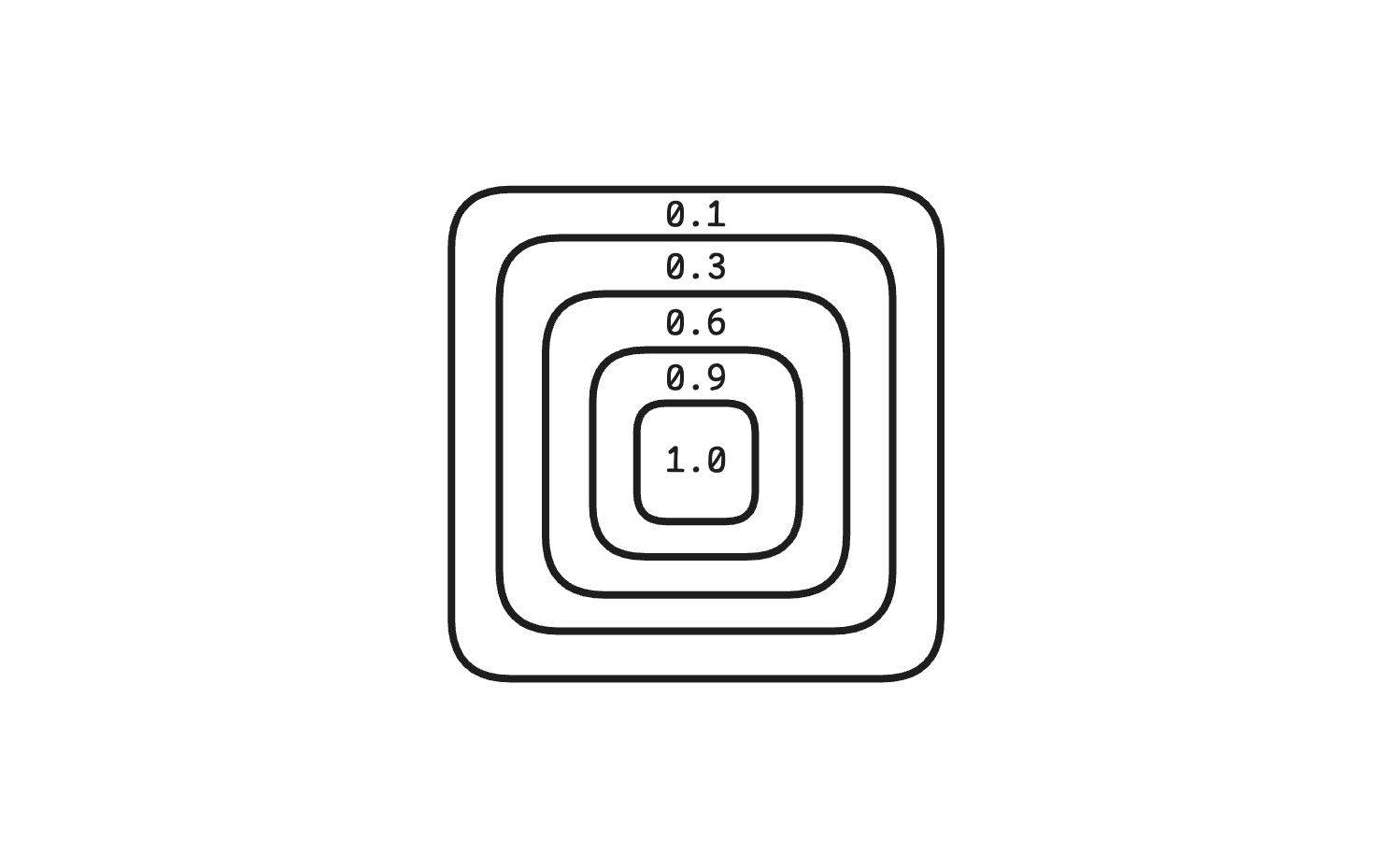
Here is another illustration of these concepts. As I mentioned before, progress might better be called delay. In any case, you can think of progress as something that helps determine how much the values generated by the noise function can be mapped into visible slices based on the current threshold value.
Enough theory, it’s time to write some code.
Preparations
Let’s start by defining the renderer type that will do all the rendering (lmao).
import MetalKit

final class DissolveRenderer: NSObject {
  init?(mtkView: MTKView) {}
}
Before we get too far, let’s add a view wrapper boilerplate to it so we can observe the intermediate result.
import SwiftUI

final class DissolveViewController: UIViewController {
  private lazy var metalView = MTKView()
  private var renderer: DissolveRenderer!

  override func loadView() {
    view = metalView
  }

  override func viewDidLoad() {
    super.viewDidLoad()

    renderer = DissolveRenderer(mtkView: metalView)
  }
}

struct DissolveView: UIViewControllerRepresentable {
  func makeUIViewController(
    context: Context
  ) -> some UIViewController {
    DissolveViewController()
  }

  func updateUIViewController(
    _ uiViewController: UIViewControllerType,
    context: Context
  ) {}
}

#Preview {
  DissolveView()
    .scaledToFit()
}
Same as for the computational pipeline, we need to create a required Metal setup: device, queue, shader functions.
final class DissolveRenderer: NSObject {
  private let device: MTLDevice
  private let commandQueue: MTLCommandQueue

  init?(mtkView: MTKView) {
    guard
      let device = MTLCreateSystemDefaultDevice(),
      let queue = device.makeCommandQueue(),
      let library = device.makeDefaultLibrary(),
      let vertexFunc = library.makeFunction(name: "vertexShader"),
      let fragmentFunc = library.makeFunction(name: "fragmentShader")
    else { return nil }

    self.device = device
    mtkView.device = device
    commandQueue = queue
  }
}
As we write the animation, we’ll make references to my previous article, which dealt with working with computational shaders and MetalKit code setup, in particular data transfer and setting states.
To establish a render pipeline, we need to create a render state. To create a render state, we need to define a render descriptor. We set the latter to allow blending so that changes in the alpha component of the color we’re going to manipulate are visible.
final class DissolveRenderer: NSObject {
  ...

  private let pipelineState: MTLRenderPipelineState

  init?(mtkView: MTKView) {
    ...

    let pipelineDescriptor = MTLRenderPipelineDescriptor()
    pipelineDescriptor.vertexFunction = vertexFunc
    pipelineDescriptor.fragmentFunction = fragmentFunc

    pipelineDescriptor.colorAttachments[0].pixelFormat = mtkView.colorPixelFormat
    pipelineDescriptor.colorAttachments[0].isBlendingEnabled = true

    pipelineDescriptor.colorAttachments[0].sourceRGBBlendFactor = .sourceAlpha
    pipelineDescriptor.colorAttachments[0].sourceAlphaBlendFactor = .sourceAlpha
    pipelineDescriptor.colorAttachments[0].destinationRGBBlendFactor = .oneMinusSourceAlpha
    pipelineDescriptor.colorAttachments[0].destinationAlphaBlendFactor = .oneMinusSourceAlpha

    do {
      pipelineState = try device.makeRenderPipelineState(
        descriptor: pipelineDescriptor
      )
    } catch {
      return nil
    }
  }
}
And don’t forget to assign a delegate to MTKView so we can handle the drawing logic.
final class DissolveRenderer: NSObject {
  ...

  private let pipelineState: MTLRenderPipelineState

  init?(mtkView: MTKView) {
    ...

    super.init()
    mtkView.delegate = self
  }
}

extension DissolveRenderer: MTKViewDelegate {
  func draw(in view: MTKView) {}

  func mtkView(
    _ view: MTKView,
    drawableSizeWillChange size: CGSize
  ) {}
}
Vertices
In the context of the render pipeline a vertex is an instance that holds the information required to draw or render something. For us it’s important to know color, position and progress. Color we define as rgba with values in range from 0.0 to 1.0.
Frankly, we will deal with this uniform range of 0.0 - 1.0 a lot.
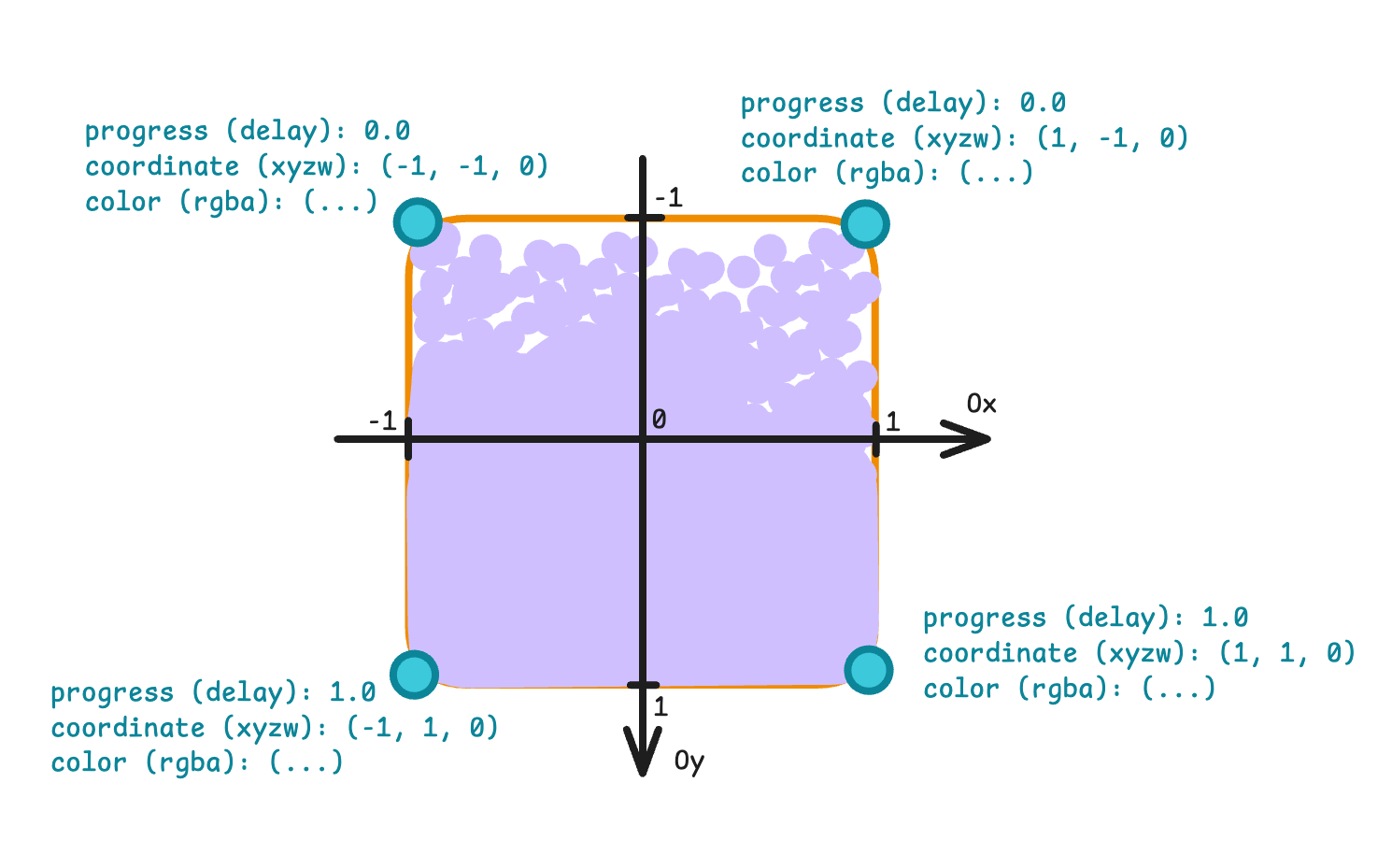
Position of each vertex is defined in homogeneous coordinates, this concept is utilized by projective geometry. Since we work with a plane, the z and w parameters have constant values across the vertices.
You can read more about projective geometry and homogeneous coordinates here.
In order not to complicate the things, we will represent the data for vertices as an array of float values. In order to make Metal understand this data, we wrap it into an instance of MTLBuffer.
final class DissolveRenderer: NSObject {
  ...

  private var vertexBuffer: MTLBuffer!
  private var vertexCount = 0

  init?(mtkView: MTKView) {
    ...

    // xyzw, progress, rgba
    let vertexData: [Float] = [
      // triangle 1
      -1.0,  1.0, 0.0, 1.0, 0.0, 0.9176470588, 0.2235294118, 0.3921568627, 1,
       1.0,  1.0, 0.0, 1.0, 0.0, 0.1058823529, 0.5019607843, 0.9490196078, 1,
      -1.0, -1.0, 0.0, 1.0, 1.0, 0.4117647059, 0.8352941176, 0.8745098039, 1,

      // triangle 2
      -1.0, -1.0, 0.0, 1.0, 1.0, 0.4117647059, 0.8352941176, 0.8745098039, 1,
       1.0,  1.0, 0.0, 1.0, 0.0, 0.1058823529, 0.5019607843, 0.9490196078, 1,
       1.0, -1.0, 0.0, 1.0, 1.0, 0.3882352941, 0.3882352941, 0.8431372549, 1,
    ]

    vertexCount = vertexData.count / 9
    vertexBuffer = device.makeBuffer(
      bytes: vertexData,
      length: MemoryLayout<Float>.stride * vertexData.count
    )
  }
}
You may notice that we give the combinations of coordinates, progress and colour 6 times instead of 4, as you might expect. Here is another picture to explain this decision.
What it boils down to is that Metal renders anything using primitives. One of these primitives is a triangle, which is defined by three vertices. In our case we want to draw a rectangle, which can be defined by two triangles. And to describe each triangle, we create 6 points - three per each triangle.
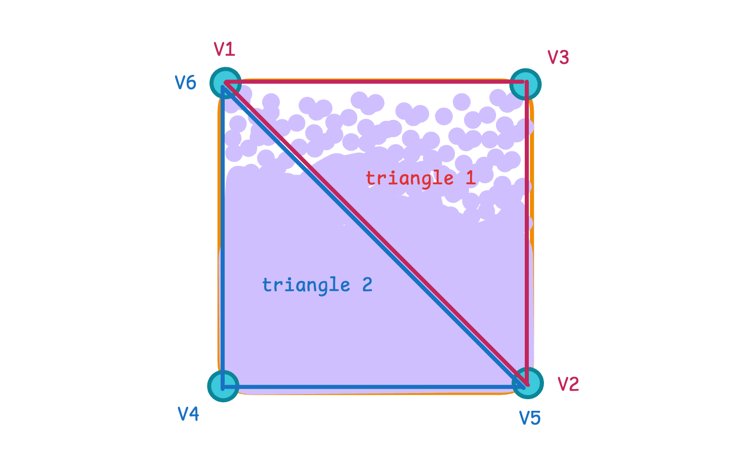
You may know that rendering consists of several components: vertex function, rasterisation and fragment function. We’ve just dealt with the vertices.
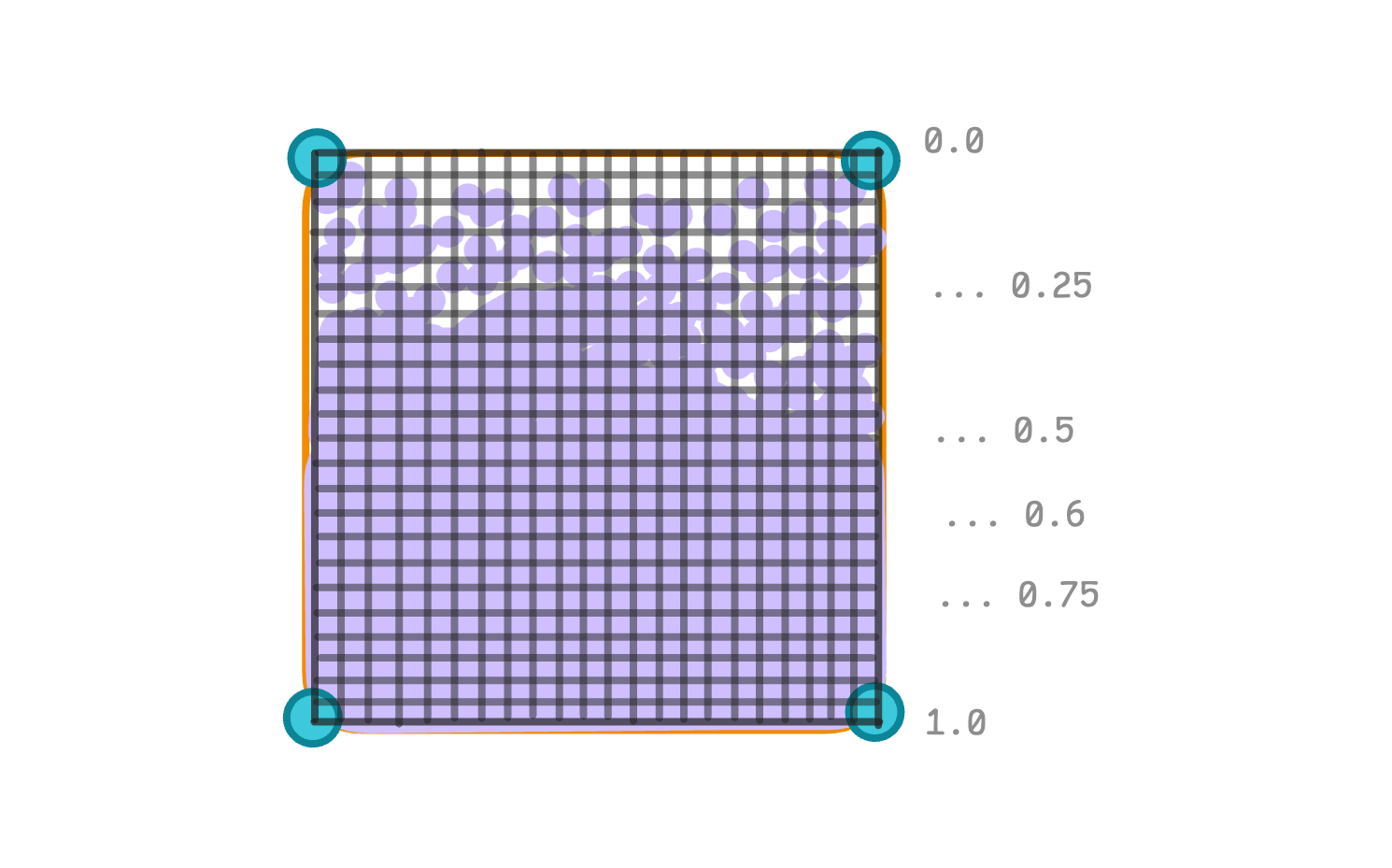
Rasterisation is automatic, and its essence is to calculate the pixels to display and interpolate the values enclosed in the vertices. Thus, each small rectangle you see in the picture is a pixel or fragment. But don’t be confused, these fragments are not vertices. At this stage, vertices are basically not important anymore, because the values from them have already been calculated and interpolated for each pixel.
If you’re not familiar with the concept of interpolation, in a nutshell it’s a mathematical method of constructing approximate values from some set of data. In our case, for example, we are dealing with the interpolated values of the animation progress between vertices from 0.0 to 1.0. In addition to the progress, we also get interpolated (mixed) colour values.
Most of the concepts regarding the render pipeline, including vertices and rasterisation, are described in this Apple guide, I highly recommend reading it.
Fragments
Let’s move on to preparing fragment shaders. To be able to send rendering instructions, we need to get an instance of the render command encoder.
func draw(in view: MTKView) {
  guard
    let drawable = view.currentDrawable,
    let commandBuffer = commandQueue.makeCommandBuffer(),
    let descriptor = view.currentRenderPassDescriptor,
    let renderEncoder = commandBuffer.makeRenderCommandEncoder(descriptor: descriptor)
  else { return }
}
Next, we define the calculation of the visibility limit. Its change will be synchronised with the supported frame rate.
final class DissolveRenderer: NSObject {
  ...

  private var visibilityThreshold: Float = 0.0
  private var timer: Float = 0.0
  var duration: Float = 2.0
}

extension DissolveRenderer: MTKViewDelegate {
  func draw(in view: MTKView) {

    ...

    timer += 1.0 / (Float(view.preferredFramesPerSecond) * duration)
    visibilityThreshold = Float(timer).truncatingRemainder(dividingBy: 2.0)
  }

  ...
}
All that’s left to do here is to encode the render state. The logic of setting values by index is the same as with computable shaders: we set a parameter by index and then in the shader we access it by the same index and with the same type.
Note the drawPrimitives call, where we specify the type of primitives required and the number of vertices to be used to draw them.
extension DissolveRenderer: MTKViewDelegate {
  func draw(in view: MTKView) {

    ...

    renderEncoder.setRenderPipelineState(pipelineState)

    renderEncoder.setVertexBuffer(
      vertexBuffer,
      offset: 0,
      index: 0
    )

    renderEncoder.setFragmentBytes(
      &visibilityThreshold,
      length: MemoryLayout<Float>.stride,
      index: 1
    )

    renderEncoder.drawPrimitives(
      type: .triangle,
      vertexStart: 0,
      vertexCount: vertexCount
    )

    renderEncoder.endEncoding()
    commandBuffer.present(drawable)
    commandBuffer.commit()
  }

  ...
}
All seems good. The only thing missing here is shaders, so let’s create them.
Shaders
Start by creating a new .metal file and defining the vertex structure. The [[position]] parameter helps us saying Metal that this value should contain coordinates of each pixel for which the fragment function will be called.
#include <metal_stdlib>
using namespace metal;

struct VertexOut {
  float4 position [[position]];
  float  progress;
  float4 color;
};
All the vertex function does in our example is build an instance of this structure. Parameter vertexID holds an index of each processing vertex, we can use it to retrieve the data we’ve passed through the buffer.
I mentioned earlier that we will not complicate the representation of the data set with additional Metal boilerplate code. Because of this, in the vertex function we need to get the data ourselves.
The maths behind the index calculation is quite simple: the data is broken down into subgroups of 9 elements. To get the next subgroup, we multiply the vertex index by the size of the subgroup (i.e. by 9). To get specific data from a subgroup, we add an offset. Thus, coordinates are on offset 0-3, progress is on offset 4, and colour components are on offset 5-8.
vertex VertexOut vertexShader(
  uint vertexID [[vertex_id]],
  constant float* vertices [[buffer(0)]]
) {
  VertexOut out;

  out.position = float4(
    vertices[vertexID * 9 + 0],
    vertices[vertexID * 9 + 1],
    vertices[vertexID * 9 + 2],
    vertices[vertexID * 9 + 3]
  );

  out.progress = vertices[vertexID * 9 + 4];

  out.color = float4(
    vertices[vertexID * 9 + 5],
    vertices[vertexID * 9 + 6],
    vertices[vertexID * 9 + 7],
    vertices[vertexID * 9 + 8]
  );

  return out;
}
Let’s add a fragment function. As you can see, it does exactly what we considered earlier: calculates the alpha value based on the noise, visibility threshold and fragment progress.
fragment float4 fragmentShader(
  VertexOut in [[stage_in]],
  constant float &visibilityThreshold [[buffer(1)]]
) {
  float2 uv = in.position.xy;

  float _delayedAge = visibilityThreshold - in.progress;

  float _noise = noise(uv * 0.1);
  float _alpha = step(_delayedAge, _noise);

  return float4(in.color.rgb, _alpha);
}
And we’ll complete the missing noise function. Generally speaking, it is the basis for the ‘pattern’ with which the effect will work. If you substitute different noise functions, you get different results. Try experimenting with different approaches to noise generation later, it really looks fun.
float rand(float2 n) {
  return fract(sin(dot(n, n)) * length(n));
}

float noise(float2 n) {
  const float2 d = float2(0.0, 1.0);

  float2 b = floor(n);
  float2 f = smoothstep(float2(0.0), float2(1.0), fract(n));

  return mix(
    mix(rand(b),           rand(b + d.yx), f.x),
    mix(rand(b + d.xy),    rand(b + d.yy), f.x),
    f.y
  );
}
In our example, the noise function takes a small rectangular section (not necessarily a single fragment) and marks it many, many times with different noise values from 0.0 to 1.0. And then as the visibility limit is increased, the parts closer to the edges of the area disappear.
You can control the scale of these slices by multiplying the noise function parameter by a factor. The smaller it is, the larger the rectangle will be and vice versa. In our example we pass uv * 0.1 which gives pretty visible and distinguishable rectangles.
That’s basically it. Run the code and check that the animation works.
Conclusion
Yeah, mentioning SwiftUI in the title of the article is a big clickbait. 99% of all manipulations were done on the MetalKit side, but what a result we got. I hope that my approach to explaining rendering will help you not to be afraid of working with Metal and will encourage you to create something great.
Here is the gist with the source code from the article. If you liked the article, please feel free to leave a few claps to make it visible to more people. And subscribe, we’ll keep picking apart Metal work and experimenting.
Thanks for reading and see you soon 🙌